Copper Foil Spiral as Counterpoise
Testing to see if a small coil can provide an effective RF ground
without the need for additional counterpoise or radials
22 July 2008
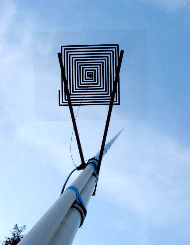
Looking up from ground level
Curiosity lead me recently to try using spiral-wound coils as ultra-portable ground systems for 1/4-wave antennas (see previous testing with 9-inch and 7-inch coils). I had three goals in mind:
1. To see if I could effectively run 40 meters from my sea kayak.
2. To determine if flat, spiral coils could be used in portable conditions to eliminate the need for multiple radials.
3. To test whether a small coil might replace the dragging counterpoise used by many HFpack members with pedestrian mobile setups.
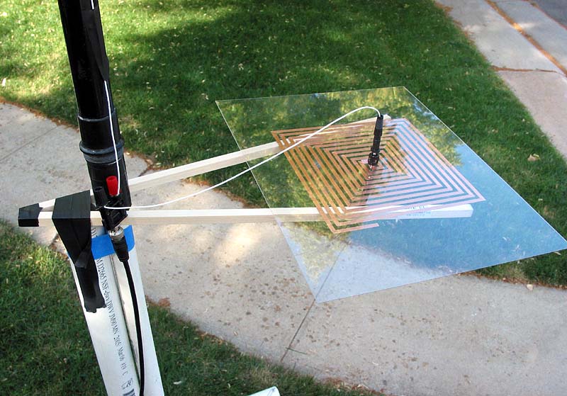
Original windings for 17 meters with 14.9 feet of foil. Eventually, I'll trim the plastic sheet that holds the coil.
To simulate a backpack setup, the coil rests 64" above ground on a makeshift shelf. A banana-to-BNC adapter joins the antenna, coil, and coax. I also drilled a hole in the center of the coil and mounted a banana jack for the ground feed wire. Both the antenna and coil feed wire are made of #22 ga. stranded wire. The coil feed wire is 14 inches in length. The antenna wire (13 feet for 17 meters and 16.5 feet for 20 meters) is supported by a 20' Cabelas fishing pole on a PVC base.
But does it work?
I tuned around on 17 meters for twenty minutes and heard
nothing! All my CQs went
unanswered. I began to wonder if the design was destined for the junk
box. But I was determined to
make a contact, so I switched to the 20 meter wire antenna and added
more foil right there in the front yard and trimmed for the new
band. Twenty was noisy at this location,
ranging from S6 to S7, and deep QSB was prevalent on most
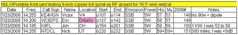
signals. Even so, I made four nice contacts. Here is the evening's logbook for Tuesday, 22 July 2008 (23 July UTC):
Listen to MP3 recording of my 13 minute contact with Nick, N7DCL, in Northern Utah.
I decided to record the last QSO, with an iRiver MP3 player/recorder placed next to the radio, as a way to document just how successful the experiment was going. Note: the first 20 seconds has Nick signing with his previous contact.
In my first QSO with KE4HGN, Victor described his antenna as a fan dipole at 45 feet but only one foot above a metal roof and said it acted more like an NVIS. He still got out fine and gave me a decent report under the circumstances.
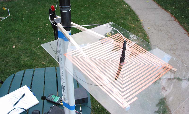
20 meter spiral
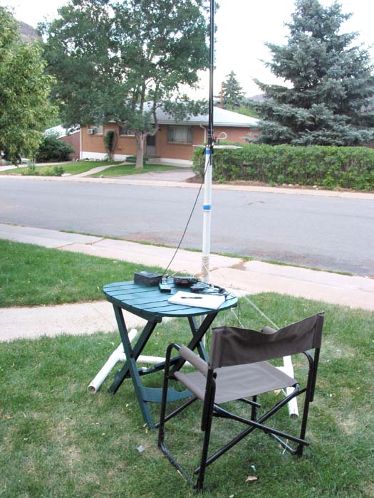
The usual front yard setup. The thin coil can be seen level with bushes across the street.
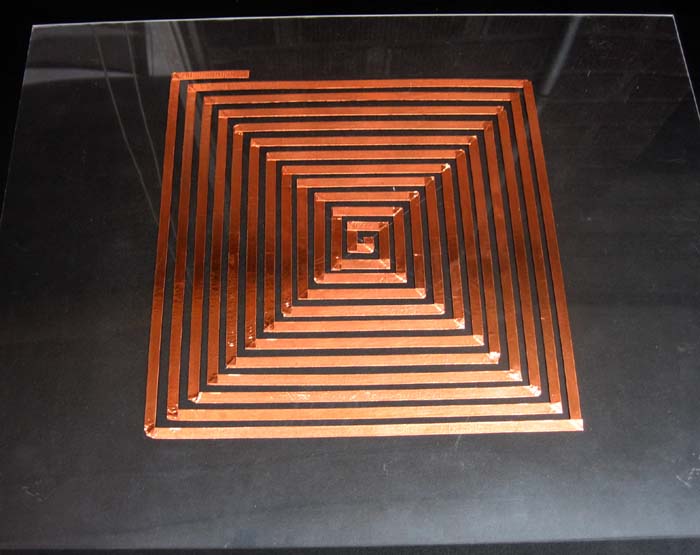
Finished coil for 17 meters containing 14.9 feet of copper foil taped to an acrylic sheet.
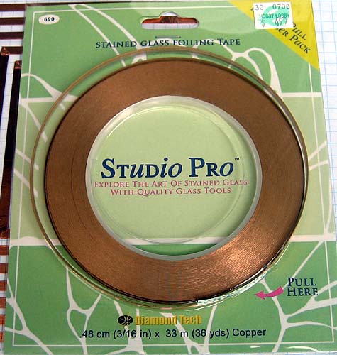
Foil is 3/16" self-adhesive copper purchased at Hobby Lobby for $4.99.
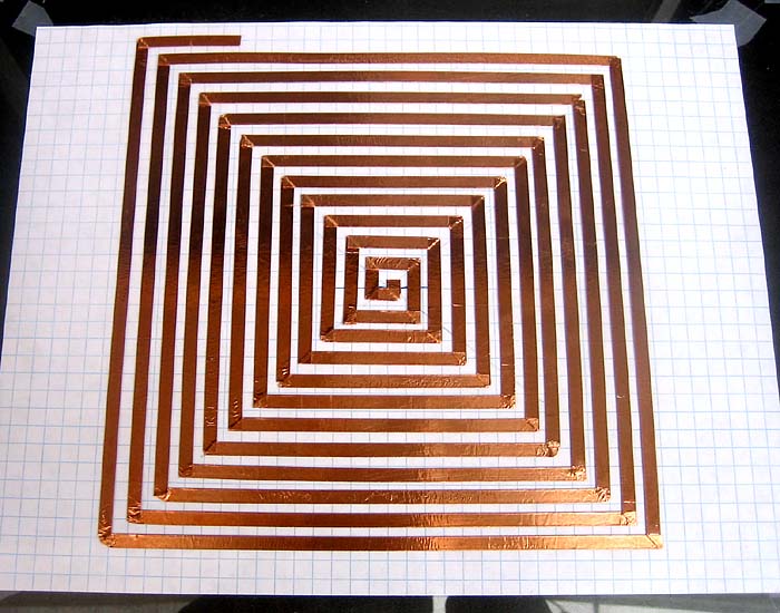
Here is the original 17m spiral constructed on a 1/16" clear acrylic sheet. Graph paper is taped to the back as a layout guide. The spacing between rows varied a bit, but is approximately 1/8" on most turns. Earlier tests indicated a need for a coil with something longer than a quarter wavelength of wire in a spiral ground plane, so I began with 15.5 feet of copper foil - enough foil to trim for 17 meters. After peeling off an inch at a time, I found a good match at 14.9 feet. The final coil for 17 and 20 meters contains 18.9 feet of foil. Hoping to make a multi-band coil, I left a space between the 17meter end and 20 meter beginning winding and bridged the gap with a small piece of copper foil.
Notes and observations:
Will this elevated-spiral-counterpoise design eventually replace the need for radials? Just think: No more tripping on each other's ground wires on Field Day. No more having pack-goats munch on your counterpoise while you're busy pounding brass (N0TU-specific reference HI). There is still further testing to be done, but I believe the small, flat coil makes an effective, compact ground system for a vertical antenna system. Of course, only real-time A/B tests will show how it stacks up to a standard radial system, but given the current band conditions, it's hard to complain about receiving 57 and 59+ reports running 5 watts!
Based on the two bands tested, it appears a rough formula can be extrapolated to determine how much foil is need for any given band:
Length = 270 / Freq. Of course, I used a 14" wire to couple the coil to the coax, and that may affect the results. Also, I used a specific width of foil along with a specific spacing and added more length than I needed to start with. My MFJ antenna analyzer makes the job of pruning and tuning much easier.
The 2:1 bandwidth on 20 meters measured 14.050 - 14.300 or 250 KHz.
Before transmitting, I documented the analyzer readings: At 14.225MHz, R = 48, X = 8, and SWR = 1.1:1
Several questions arose while I worked on this project:
1. Would wider spacing of the copper foil give a better bandwidth as Bill Petlowany suggested in his World Radio article?
(My goal was only to produce a compact design.)
2. Would a non-inductive serpentine winding, like the ones used by Monty Northrup, N5ESE, to shortened dipoles, produce similar results?
3. How would SWR vary at different heights above ground?
4. How would a side-by-side A/B test compare against a single, dragging counterpoise?
5. Would a thicker spiral stand up to - or even work - at high power?
The point is that it works - at least to my satisfaction.
Maybe I should name it the ESP (Elevated Spiral 'Poise) ground system. . . . Maybe.
73,
Jake, NØLX
.....