End-fed, Inverted "V" for 17-20-30-40 Meters
Four Band Lightweight Antenna
made 08-05-2006
There are four antennas in here!
barrel connectors used for jewelry making
dipole center
mast height is 19' 2" overall
Four Band Lightweight Antenna
made 08-05-2006
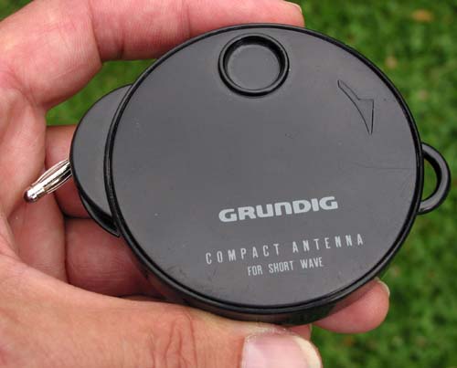
Here is a 4-band antenna that rolls up
into an small Grundig antenna case. I pulled out the original wire and
replaced it with 67 feet of 28-ga. Teflon-coated wire.
It is a full halfwave end fed inverted V for four bands. I designed it
to be backpackable and uses
the PVC support base
I
made earlier. The base and mast break down to no more than 16" lengths,
and as
you can see, the antenna itself takes up little space. There are
different lengths for each band, and all sections screw
together. The banana plug plugs
into a homebrew L-C tuner at one end of the antenna.
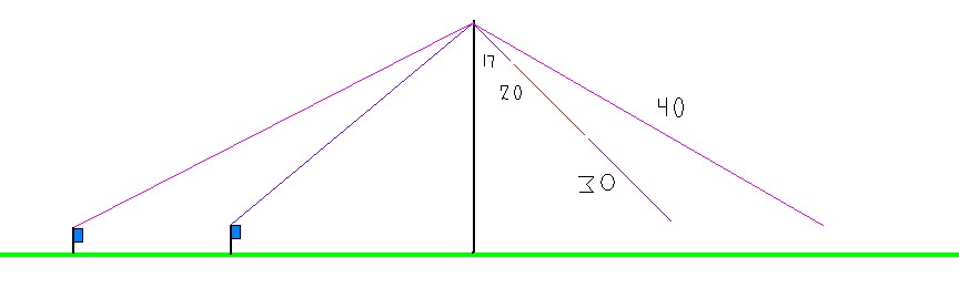
There are four antennas in here!
Here is a crude diagram showing how I
have arranged the different bands. The blue rectangles are the feed
points. Note: I don't actually set up everything as seen here. Either
the 40 is up, or the 17-20-30 wire - not both at the same time. For 17,
20 and 30 meters I set up at the inner feedpoint. The 17 meter
antenna is mostly a 1/2-wave sloper with an extra 3 feet going down the
other side. On 20 it is much the same, just more wire on the side
opposite the feedpoint. Only 30 and 40 meters are fully symetrical
Vees, but all wires are a full 1/2-wave for the given band. If I am on
17, for example, a thin guy rope supports the three feet of wire
on the right and substitutes for the missing 20 m and 30 m wires.The 40
antenna is simply ALL of the separate wires screwed together. To tune I
use my homebrew matching unit.
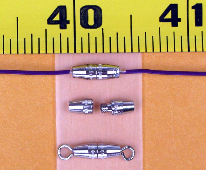
The photo below shows the barrel
connectors I used for changing bands. They come with swivel loops, but
I removed them and soldered the 28-ga. wire into the hole left by the
loop. They are
only about 3/8" long, and quite interesting to work with (small and
slippery with tapered ends). Here is a picture showing the connector -
with the loops removed - and with wires soldered on.
barrel connectors used for jewelry making
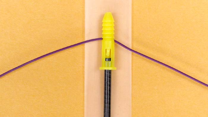
To support the center of the antenna, I
remove the tip section of the 14' Cabelas graphite pole because it is just too flimsy. A plastic
screw anchor holds the wire in place. The anchor is split halfway down, and the
antenna wire slides into it.
dipole center
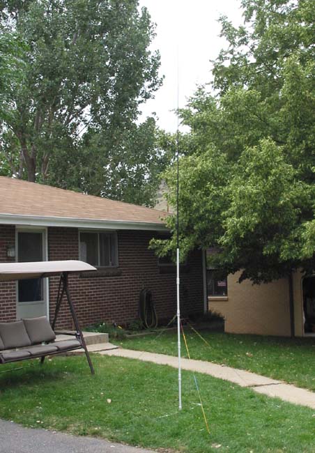
Below is a photo of the mast and
base set up. I have added two more 16" vertical sections to the
original design. Because the 1/2" PVC is not quite sturdy enough to
support this much height, I used some light string as guys. Now
it's very stable,
even with the 40-meter wire draped over it.
mast height is 19' 2" overall
The setup is a bit unconventional and
has yet to be tried except with the MFJ analyzer where I was able to
get a 1.0:1 match on all bands. It is a bit low for 30 and 40 meters,
but I wanted a compact, self-supporting antenna system good on multiple
bands for treeless hikes and campouts. I could have added 10, 12 and 15
meters, but mostly wanted to see if I could cram a 40 meter antenna
into that small Grundig case including all the barrel connectors, and
three more connectors might not have fit.
I hope to test the antenna on all four bands soon.
Jake, NØLX
I hope to test the antenna on all four bands soon.
Jake, NØLX
....