2 June 2008
This may be the first ever attempt at feeding a saltwater antenna*(see note at bottom of page) as a halfwave at the high-impedance end. The antenna consists of 33 feet of PVC tubing filled with over two gallons of a heavy concentration of saltwater. In this case, I used calcium chloride at 2.5 pounds per gallon of water.
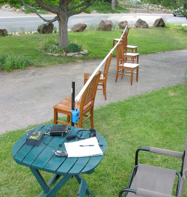
The benefits, if set up as a vertical, include no ground/counterpoise required and maximum radiation well above ground. For this test, I opted for a horizontal configuration for simplicity. Seen below is the 33-foot antenna held above ground with six dining room chairs only 37 inches above ground: not optimal, but only meant as a temporary setup. I hoped to measure the feedpoint impedance and see if I could feed the end with my homebrew L/C matching unit.
Continue down the page for more details and an interesting R/X/SWR graph.

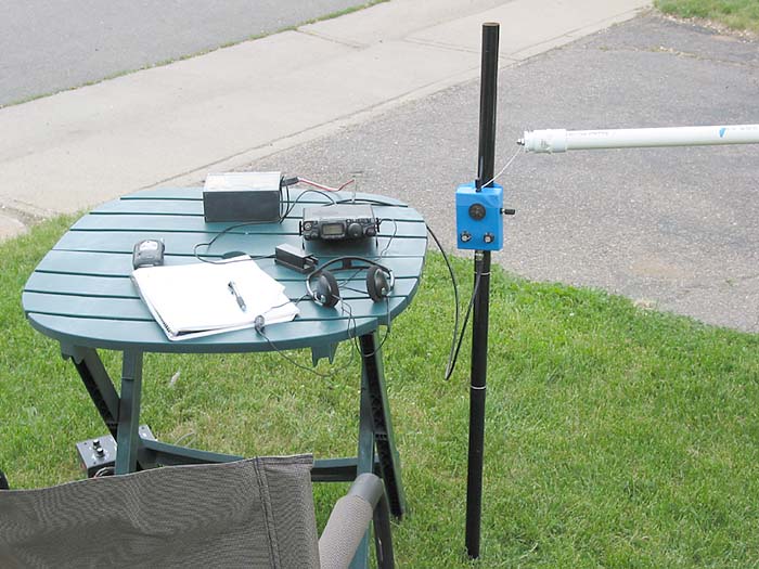
Here is a view of the entire setup showing my FT-817, Palm mini paddles, the (blue) matching unit, and the antenna.
Here is a side view of the equiptment. Note the lack of counterpoise of other ground connections.
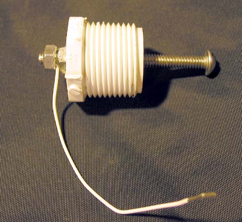
Here is a closeup of the end cap. It shows the stainless steel bolt that acts as a probe for transferring RF energy into the liquid.
I made some measurements with an MFJ-259B analyzer. Here is a graph with the results.
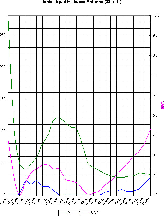
Notice the double resonance points at 12.800MHz and 14.225MHz (magenta line) where R=50 and X=0. Note also the lack of reactance (X) between 13.575MHz and 14.400MHz (blue line) and again everything below 12.800MHz. The antenna was built with the standard dipole formula (468/frequency) which explaines the expected resonant point. If the second resonant point of 12.800MHZ is used, the correct formula for a saltwater half-wave would be 422.4/frequency. Interestingly, I have previously measured the optimal length for a quarter-wave ILA to be around 210/frequency, or virtually half the 422.4/f indicated by the second resonance dip.
Does this mean the true resonant point for this antenna is actually at 12.8 MHZ???
I am sure the graph would have looked differently had the antenna been mounted up in the clear or in a vertical configuration. Not shown on the graph is the calculated feedpoint of the antenna. Based on the turns ratio I had to use on the matching unit, it calculates to 880 ohms. Not very high for a true end-fed halfwave, but the lower value may be due to its close proximity to ground.
BUT DOES IT WORK?
As always happens when I build a new antenna, I tell myself I will only
test it with the analyzer, but when it tunes up so nicely, I cannot
help but run inside and grab the radio gear for an on-air test. With
such a seriously low antenna, I expected a fair receive ability but no
contacts. I first tried the microphone, but signals were not very
strong, and I heard many complaints of deep fading from those I did
hear. As expected, I made no contacts on phone. Then I hooked up the CW
paddles and tuned around the band. I heard Gary, N2ESE, in New Jersey
who had just lost a contact to QSB. Logic said a horizontal antenna for
20 meters, only three feet off the ground and fed with five watts, will
not make it 1,400 miles, but I called him any way. Gary came back with
a 459 signal report!! The intent here was not to create a gigantic, unwieldy, plastic antenna loaded with 20 pounds of saltwater, but to answer the question of whether it is possible to load an ILA at the high impedance point. My next project will be an Ionic Bobtail Array consisting of three, phased 1/4-wave ILAs, joined at their tops by a pair of 1/2-wave (wire) phasing lines. It, too, will be voltage fed at the base of the center antenna. At 16.5 feet tall, it will be much more manageable and hopefully will show some gain and directivity.
73,
Jake, NØLX
www.n0lx.com
* Special note: the concept of transmitting through saltwater was the creation of the "Tesla of Green Bay," Mr. David Hatch, N9ZRT.
.....